

Steven F. Weiner, MD describes the benefits of using ultrasound imaging in facial aesthetics, including guiding needle injections and identifying vascular occlusion

The Aesthetic Clinique
2050 West County Highway 30A, Santa Rosa Beach, Florida, United States
email: info@theclinique.net
ULTRASOUND IS USED UBIQUITOUSLY throughout the field of medicine. Almost all specialties have embraced ultrasound as a quick, painless, and relatively inexpensive diagnostic tool to assist the clinician in determining pathology, anatomy, and assisting in diagnostic or therapeutic procedures. The field of aesthetics has been late to embrace the power of ultrasound, but it is slowly happening now.
The roots of ultrasound in facial aesthetics can be traced back to Dr Leone Schelke, a cosmetic physician in Amsterdam. She founded a filler complications clinic at The Erasmus University in Rotterdam over 10 years ago. She was seeing several complications from fillers, particularly (now banned in Europe) permanent fillers, and needed a better way to characterise these fillers and their location. There were also vascular occlusions being referred to the clinic from all over Europe. Dr Schelke found that when using ultrasound, she could treat these patients much more effectively and quickly, without sending them out for expensive testing such as CT scans or MRI. Her clinic now sees 15 patients, 3 days per week, and treats 10 or more vascular occlusions (VO) per month.
Ultrasound is useful in aesthetics for the following reasons:
■ Determine anatomy (facial assessment): vascular, fat pads, muscular
■ Evaluate previously placed fillers: composition and location
■ Evaluate vascular flow, vascular mapping, and evidence of vascular occlusion
■ Guided filler injections
■ Guided therapeutic injections such as hyaluronidase.
ULTRASOUND TRANSDUCER (PROBE)
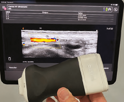
The ultrasound transducer emits a sound wave which is reflected by the tissue being examined while the echo is detected by the transducer. In essence, the transducer is both a transmitter and a receiver of ultrasound. It operates on the piezoelectric principle, converting electrical energy into mechanical energy (sound) and when received, converted back to electrical energy.
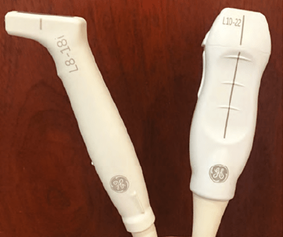
There are various probes including linear, convex, and phased array, used in ultrasound and each has its particular advantages. The linear array probes are recommended for the face due to their superficial focus versus the convex array probes which focus much deeper (liver, bladder). Another probe characteristic is their frequency. The higher frequency (HF) probes will give more detailed images but are limited in their depth of penetration (up to 3cm). Higher frequency probes are more sensitive to attenuation as they travel through tissues than the lower frequency probes, so HF probes are best suited for superficial examinations such as the face. High frequency (HF) probes range from 10-22MHz. There are variations of the aperture (footprint) designs as well with smaller and larger areas. Ultra-high frequency transducers (up to 70MHz) have been recently developed and they could potentially be the next frontier, but currently they are mainly used in research and their utility in clinical practice is limited due their cost (>$130,000). The GE hockey-stick transducer is 18 MHz and is ideally suited for facial ultrasound, while the minimum frequency transducer should be 10 MHz in the author’s opinion.
Transducer orientation is standardised across the industry. There is a notch or marker on one end (when viewing on its long axis) of the transducer that should always be oriented to the patient’s right when evaluating in the transverse or horizontal plane. It will show up on the ultrasound image on the left side. If evaluating in the sagittal or vertical plane, the indicator should be oriented to the head. In the midpoint of the probe, there is always another indicator, and this shows up on an ultrasound image in the middle of the screen.
ULTRASOUND TERMINOLOGY
In order to communicate ultrasound findings, some basic terms need to be defined.
■ Anechoic: Image appears black on ultrasound. The sound wave is not reflected. Characteristic of fluid, water, and abscess.
■ Hypoechoic: Image appears dark grey on ultrasound. The sound wave is minimally reflected back to the transducer. This is typical for muscle and glands, such as parotid. Sometimes large nerves will appear hypoechoic as well.
■ Isoechoic: Image appears light grey and is similar to surrounding soft tissue. The sound wave is moderately reflected back to the transducer. This is typical for fat, dermis, and subcutaneous soft tissue.
■ Hyperechoic: Image appears white on ultrasound. The sound wave is highly reflected back to probe. This is found in bone, teeth, and areas with dense collagen such as ligaments.
■ Homogenous: Structure being evaluated is uniform in echogenicity.
■ Heterogenous: Structure being evaluated is a combination of more than one echogenicity.
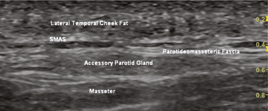
ULTRASOUND ANATOMY
The anatomy of the skin, muscles, vessels, fat pads, nerves, ligaments, and fat pads are visible to an experienced ultrasonographer.
Skin will appear hyperechoic in the epidermis and isoechoic in the upper dermis (~papillary dermis). The lower dermis (~reticular dermis) appears hyperechoic due to the high density of collagen fibres. The skin thickness is highly variable throughout the face and is also dependent on sex and ethnicity. Skin is always at the top of the ultrasound image and must be differentiated from the gel used (which is anechoic).
Muscle appears hypoechoic due to its water and blood content. Movement of the muscles can aid in their identification. Fascia and tendons will appear in and around the muscles and reflect the sound waves, appearing hyperechoic.
Fat will appear isoechoic or hyperechoic depending on the amount of fibrous tissue within the fat. Fat is seen in the subcutaneous layer, superficial fat pads and deep fat pads. The deeper fat pads are attached to the periosteum. The superficial fat pads lay superficial to
he SMAS layer. There are differences in echogenicity of the two fat layers (deep and superficial) due to differences in fibrous tissue and density.
Ligaments/tendons will appear hyperechoic on ultrasound. Ligaments can be challenging to visualise until one is highly experienced with facial ultrasound and has extensive knowledge of facial anatomy.
Nerves fascicles will appear hypoechoic and the connective tissue will be hyperechoic. Larger nerves such as mental, facial, and infraorbital are easier to visualise than smaller, more peripheral branches.
Glands (i.e. parotid) appears hypoechoic and mostly homogenous.
Bone/cartilage will appear as hyperechoic on ultrasound and will be the bottom of most images. Structures/tissue close to bone/cartilage will be hard to see because the sound waves are reflected nearly completely by the bone.
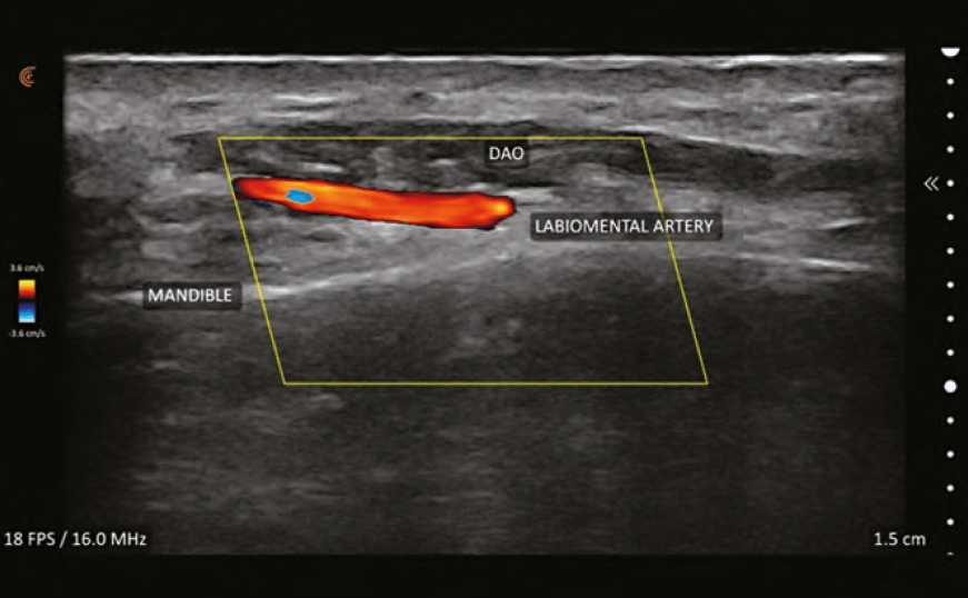
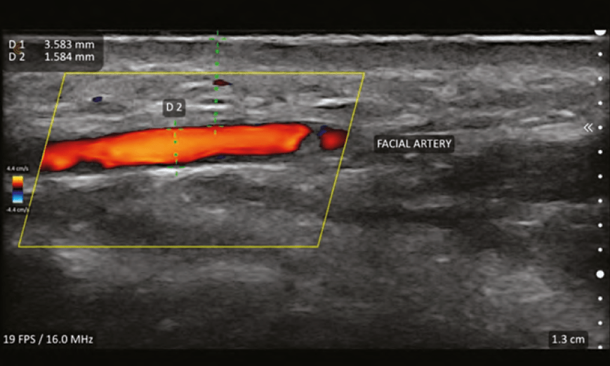
ULTRASOUND VASCULAR ANATOMY
Perhaps the single most important feature of facial ultrasound is the ability to identify the vascular structures. This requires the ultrasound to have duplex capabilities. Duplex refers to two modes being used simultaneously, B-Mode and Doppler. Measurements obtainable with duplex are:
■ Establishing flow, no flow, or turbulent flow within a vessel (patency vs occlusion/clot)
■ Determining whether a vessel is an artery or a vein
■ Determining the direction of flow (towards or away from the transducer)
■ Determining the speed of blood flow.
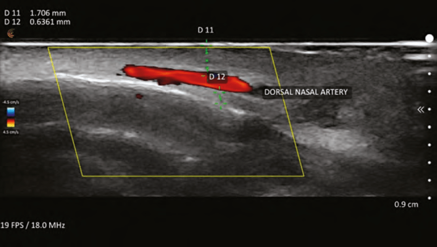
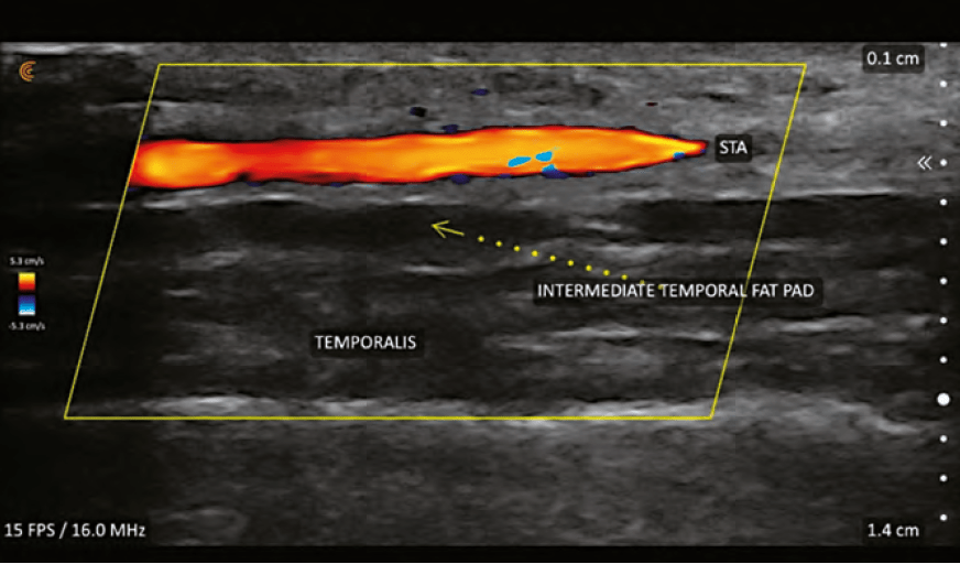
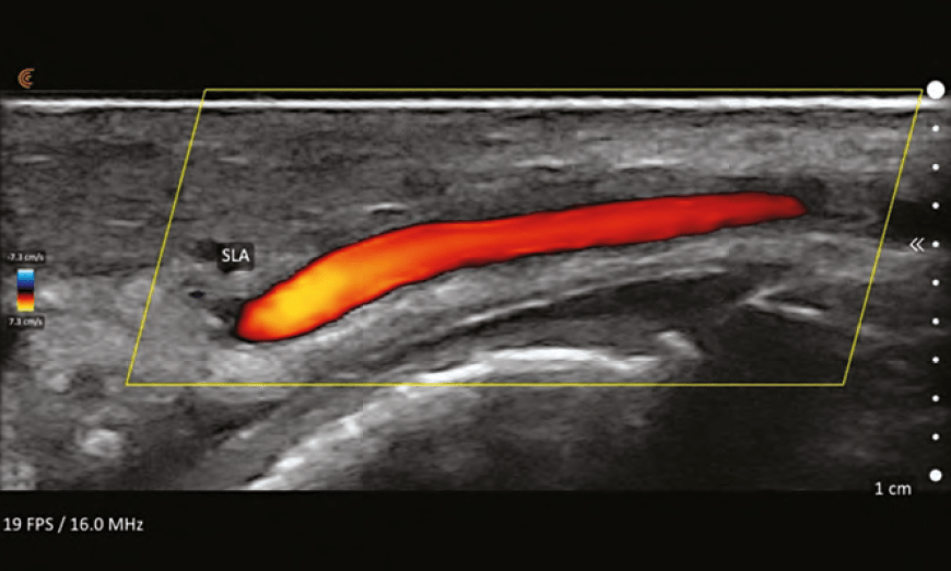
Vessels will appear shades of blue or red; the brighter
the colour, the faster the flow. While it might seem intuitive that the veins are blue and arteries are red, this is not true. Blue colour equates to flow away from the probe and red equates to flow towards the probe. By convention, arteries are red and if they appear blue, colour inversion can be performed to change them to red. Turbulent flow is represented by mixing of blue and red within a vessel and sometimes represent an area of vascular spasm as occurs during ineffective flow during vascular occlusion. It may also represent areas of plaque-causing nonlinear flow.
Determining arteries from veins can be performed by using pressure (compression technique) on the transducer. The vein will collapse while the artery will stay patent due to its muscular walls, with mild pressure. Other methods include evaluation of the vessel’s waveform and velocities using spectral Doppler ultrasound analysis.
Colour flow Doppler is only visualised inside the colour Doppler Sampling Window or ‘colour box’. It is important the box is set to the proper depth of the vessel(s) being interrogated. The size of the box can be sized to a small area where the frame rate is maximised (smoother and higher resolution image) or a larger box (where the frame rate is slowed) to see more of the vessel or several vessels. Colour box ‘steering’ is important to optimise images and is performed by changing the box from being perpendicular to the vessel to angled at 20–25 degrees to the flow.1 The optimal insonation angle (angle of ultrasound beam relative to the vessel of interest) is <60° and the closer to 0° the better. Turning the colour gain levels up allows for better visualisation of vessels but should be lowered if there are random colour spikes outside the vessels or bleeding of the colour outside the vessel walls.
VASCULAR MAPPING
The practice of vascular mapping is using ultrasound to determine position, size, and depth of critical vessels in the anticipated area(s) of treatment. An extensive knowledge of the arterial anatomy and its possible variants is essential to master vascular mapping. An example of vascular mapping is evaluating the depth and position of the angular artery in the pyriform area. Typically, the artery is at a level of 5mm in this area, but variants have been shown to run along the periosteum. Knowing the position and depth will give the injector information to perform a safer injection in this area and assist in preventing adverse events.
DERMAL FILLER IMAGING
Evaluating the placement and characteristics of previously injected fillers is beneficial to the aesthetic injector. There are many instances of patient-perceived asymmetries, swelling, and firmness, which can be further evaluated using ultrasound in conjunction with a physical exam and comparison photographs. An experienced ultrasonographer is able to determine the position of filler (for example periosteum, subdermal, in deep or superficial fat pads). Complications such as abscess, granuloma, pseudocyst, and nodules can also be evaluated using ultrasound.
DIFFERENTIATING FILLERS ACCORDING TO COMPOSITION
Dermal fillers will often have characteristic ultrasound echogenicity. There are often artifacts associated with the fillers seen on imaging as well.
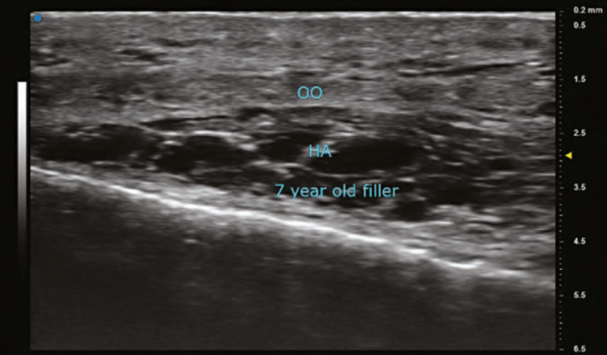
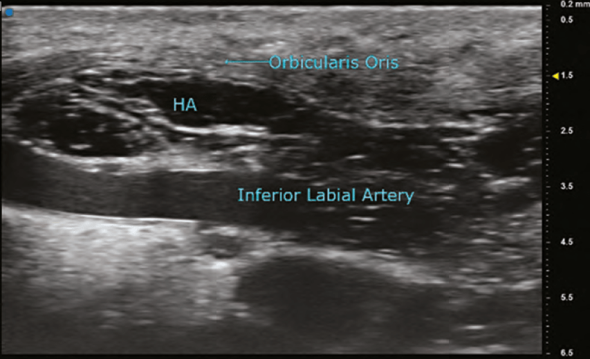
HYALURONIC ACID (HA)
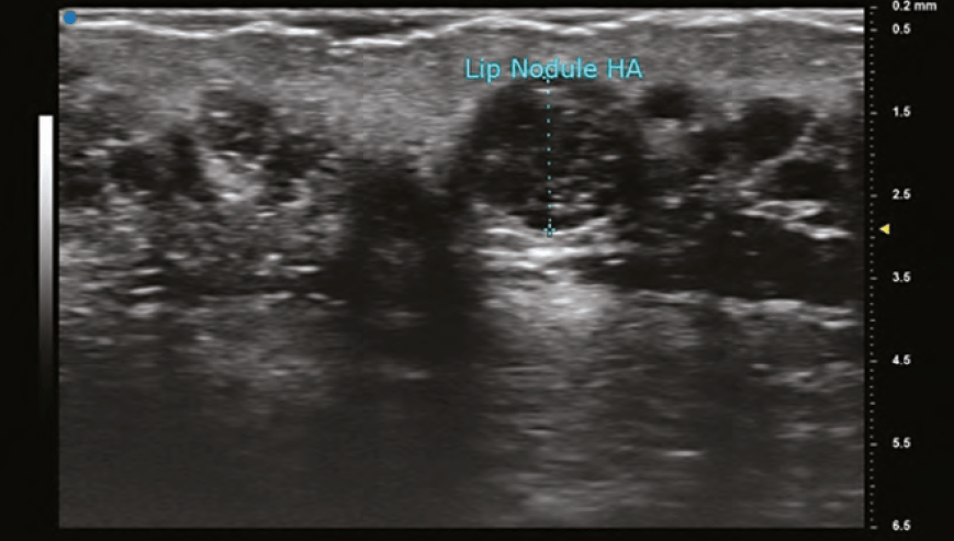
The findings on ultrasound is highly variable for HA depending on the duration it has been within the tissues. A newly placed HA will have high water content and therefore poorly reflect the sound wave and appear anechoic (black). As HA resides in tissue longer, its water content decreases and gradually becomes hypoechoic (dark grey), and then isoechoic (light grey). The shape of the filler is sometimes seen as a pattern of repeated pointed ovals or ellipses, regardless of whether it was placed with needle or cannula. In general, its most common finding is a rounded anechoic deposit.
CALCIUM HYDROXYLAPATITE (CAHA)
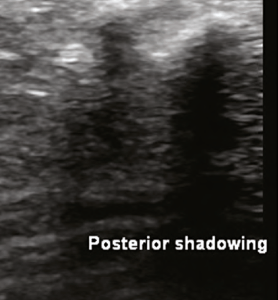
This biostimulatory filler is composed of microspheres of CaHa, measuring 25-45 micrometres, and carboxymethylcellulose. In the tissues, CaHa appears as hyperechoic microspheres. If there is a depot injection, there is a large hyperechoic image with posterior shadowing. Collagen will gradually emerge in surrounding tissue over the ensuing months and will appear hyperechoic. The hyperechoic microspheres can be imaged for a variable time period (months – years) after injection.
POLYMETHYL METHACRYLATE (PMMA)
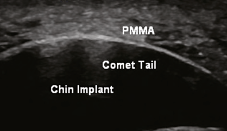
A biostimulatory filler composed of microspheres of PMMA, measuring 40 microns, and bovine collagen. Ultrasound findings are similar to those found in CaHa. The microspheres are hyperechoic and there is a corresponding collagen response which is also hyperechoic. Often, there is also comet tail artifact.
POLY-L-LACTIC ACID (PLLA)
Another biostimulatory filler, this one is a polymer measuring 40–63 micrometres and is mixed with lidocaine and water or saline prior to injection. The large water/saline content causes this filler to greatly diffuse through the tissue that is injected. Findings on ultrasound show a diffuse hyperechoic ‘cloud’ of collagen.
SILICONE OIL
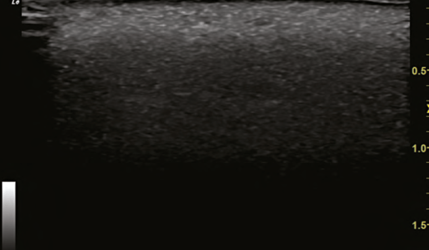
This biostimulatory filler is a non-biodegradable synthetic substance typically injected in a 0.01ml microdroplet technique. The tendency is for this product to spread diffusely through the soft tissue. It has also been known to create late granulomatous inflammation, sometimes 10 or more years after injection. The ultrasound finding is labelled as a ‘snowstorm’ where there is diffuse hyperechoic filler (collagen and silicone oil) with the inability to visualise normal anatomic structures deeper due to posterior acoustic reverberation. Finding a snowstorm on ultrasound would dissuade most practitioners from injecting, due to fear of conjuring up a difficult to treat inflammatory response.
ULTRASOUND ARTIFACTS
The following are examples of artifacts that can present in an ultrasound.
■ Posterior shadowing: A signal void seen deep to highly reflective objects such as CaHa or bone
■ Comet-tail: Apparent when evaluating a highly dense hyperechoic object (PMMA) and is seen as a hyperechoic artifact that is wider near the object and becomes smaller in the deeper tissues
■ Mirror image: Occurs when there is a highly reflective surface in the path of the primary beam
■ Posterior enhancement: Increased echogenicity seen posterior to fluid/cystic structures due to attenuation of beam less than surrounding structures leading to the time gain compensation to overcompensate.
VASCULAR OCCLUSION
Perhaps the most valuable contribution that ultrasound has made to the field of aesthetics is the detection and treatment of vascular occlusions (VO) caused by filler injections. While the early diagnosis of VO is usually clinically apparent (blanching, poor capillary refill, livedo reticularis), there are occasions where it is not as obvious. An example of this dilemma is differentiating between a bruise and a VO. Ultrasound can rapidly establish the existence or non-existence of vascular flow in these cases and allow the patient and practitioner to rest easy if there is flow.
In the instance of VO, ultrasound can elucidate the areas of occlusion and the offending agent, the pocket of filler. The practitioner must also be familiar with angiosomes and the choke phenomenon, and access if there are areas of distal choke compounding the VO at the primary injection site. The angiosomes of the face are connected to both true and choke anastomosis. When a VO occurs, a choke vessel can close as a protective mechanism to prevent further spread of the filler.2 For the injector, the area of choke must be evaluated with ultrasound and potentially treated with hyaluronidase, even if distant from the original injection site. Recent literature, also by Taylor, shows that AV shunting can contribute to the ill effects of VO because most of the veins in the face are valve-less and retrograde flow in veins is possible.3 The veins in the glabella area are particularly at risk for blindness according to Taylor, relating to fixation of the vein walls and lack of valves.
Treatment of VO caused by HA filler is performed using hyaluronidase. The widely accepted protocol is one developed by Dr Delorenzi, ‘High Dose Pulsed Hyaluronidase’.4 This protocol is based on the notion that there is rapid transarterial diffusion of hyaluronidase as was noted in a publication by Dr Delorenzi in 2014.5 This study was performed on cadaveric arteries and might not be clinically relevant. The basal lamina of the arteries changes within 15 minutes of death and might alter the diffusion characteristics in the cadaver model.
In an abstract presented at the Non-Surgical Symposium 2019 by Drs Papadopoulos, Sundaram, and Magnusson6, there was evidence to contradict Dr Delorenzi’s transarterial diffusion paper.5 During an abdominoplasty, arterioles were isolated of 1–2mm in diameter and tied off. HA filler (0.3–0.5 cc) was injected into the lumen of these vessels (2 vessels per patient, six patients). Hyaluronidase (750 units) was bathed extraluminally for 5 minutes. There was no change to the intraluminal HA by palpation during this time. Injections of hyaluronidase directly into the lumen of the vessels caused rapid degradation (seconds) of the HA filler. This study is consistent with in-vitro studies of hyaluronidase which show quick responses to hyaluronidase for many of the HA fillers in doses far less than what is required clinically using Dr Delorenzi’s High Dose Protocol. As a matter of fact, Dr Delorenzi mentioned ultrasound as the future of treating VO in his lecture at The Miami Cosmetic Surgery Conference in February 2020.
Another example of the power of ultrasound in treating VO was during a visit by the author to the Complications Clinic at Erasmus. A patient was treated for a nasal VO at an outside clinic with 3000 units of hyaluronidase and presented to the Complications Clinic the following day. The nose continued to show signs of occlusion and these were identified using ultrasound. Using ultrasound guidance, the areas of occlusion were dissolved with 120 units of hyaluronidase, directly into the occluded arteries. The patient had immediate resolution of her occlusion documented with duplex ultrasound and improvement clinically as well. The following day, her nose appeared normal.
It is the author’s opinion that the majority of VO incidents are related to the intravascular placement of filler and not extravascular compression. The exception to this statement would be in areas where compartment syndrome is possible, such as in the nasal tip. This belief further supports the use of guided hyaluronidase injections intraluminally versus flooding the area of VO extravascularly.
Recently, sodium thiosulfate (STS) has been advocated for treating nodules or VO’s related to CaHa.7 There is one paper in a porcine model showing reduction of CaHa when treated with STS and another showing effectiveness in a human volunteer with a case report.8 In communications with Dr Schelke, she reported effective use of STS in a limited number of patients with VO from CaHa.
ULTRASOUND-GUIDED INJECTIONS
Duplex ultrasound enables the clinician to perform guided injections for placement of filler in a safe plane or depth and to better visualise injections of hyaluronidase to resolve VO. While routine use of guided injections for fillers sounds ideal, the procedure should be reserved for complex cases or in areas of high risk for blindness or VO due to the significant time requirements with these injections.
To perform ultrasound-guided injections, a sterile transducer cover and sterile ultrasound gel are required. Prior to slipping the cover over the transducer, the gel must be placed on the footplate. The patient should be positioned between the practitioner and the ultrasound display to limit body and head movements of the operator to keep the transducer stable. There are transducers that are better adapted for injections which have attachments to allow for the injection needle to be connected and stabilised in the view of the ultrasound.
A feature of some ultrasound models is needle enhancement. This built-in algorithm maximises the received reflections by steering the ultrasound beam precisely perpendicular to the needle. The needle appears as a bright line image. An oblique line is placed on the monitor and the needle should be directed towards this line (it can be rotated in the opposite direction without the need to move the transducer if needed).
‘In-plane’ injections are performed with the needle along the long axis of the probe and allow for full visualisation of the needle from the skin to the target area. ‘Out of plane’ injections are when the needle is perpendicular to the long axis of the transducer. Only the tip of the needle is visualised in out of plane injections which is not optimal, but the flexibility of various angles and insertion points can be advantageous.
In treating an HA VO effectively, the occluded vessel and associated filler pocket should both be visualised. If the VO is treated successfully, the near-immediate flow should be re-established in the occluded vessel. Keep in mind that there are differences in sensitivity to hyaluronidase amongst the various approved HA fillers.9 There are several studies that have concluded that higher cross-linking leads to more difficulty dissolving the filler. Other factors that probably contribute to resistance are monophasic, time from injection, Vycross technology, and Hylacross technology. (9-11) In these more difficult fillers, higher doses of hyaluronidase and multiple treatments are typical.
Failures related to hyaluronidase can be related to HA pseudocyst formation where the wall is partially impermeable to the hyaluronidase. In these cases, ultrasound-guided injections will significantly improve the dissolution of the undesired filler.
ULTRASOUND MEASUREMENTS
Highly accurate measurements are obtainable using the ultrasound down to 0.1mm or less in some devices. Measurements are helpful to determine the depths of critical arteries to allow for safer filler injections. Also, it allows the provider to follow the patient’s response to treatment, i.e. skin thickness, submental fat thickness, and progression of a granuloma/abscess. Multiple measurements can be performed on the same image as well as oval/elliptical circumferences and cross-sectional areas.
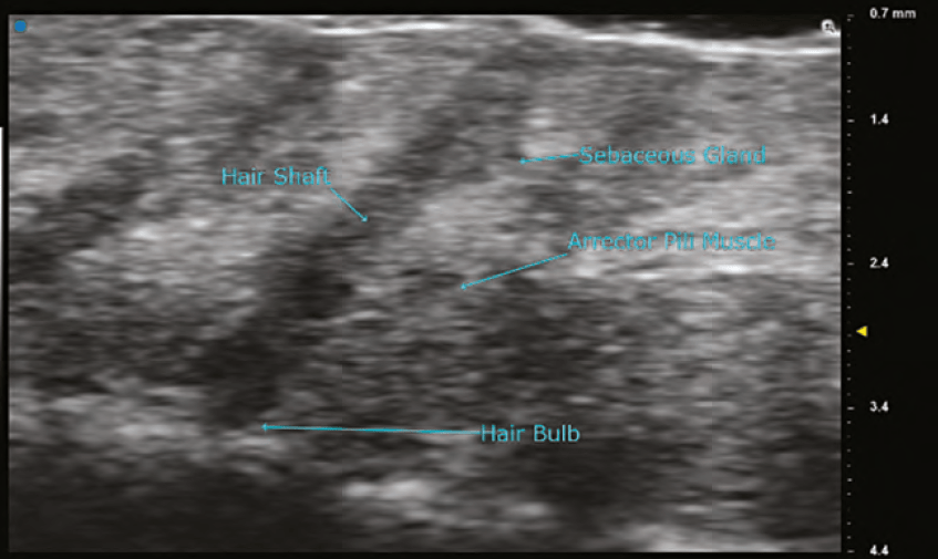
ULTRA HIGH FREQUENCY ULTRASOUND
Ultra high frequency ultrasound has transducers with frequencies of 48MHz and 70MHz. The images of these probes can show the various layers of the skin and its organelles with extreme detail. The anatomy of a hair follicle with its associated sebaceous gland, erector pili muscle, and hair bulb are readily visible. Details of neoplasms of the dermis can be evaluated, and surgical margins can be assessed preoperatively. Using the B mode, red blood cell flow can be seen in dermal and superficial vessels and is the preferred method to visualize vascularity. The limitations of the 70 MHz transducer are that the depth of imaging is < 10mm and the colour Doppler is not as sensitive as it is in the high frequency probes. In the author’s experience, visualization of fillers is far superior using the 48MHz and 70MHz probes when compared to high frequency probes. Resolution with the 70MHz probe is stated to be as small as 30 microns.
PORTABLE (POCKET) VASCULAR DOPPLER
Pocket Dopplers are inexpensive devices used to determine the existence and relative strength of flow within a vessel (artery or vein). The probe is placed on the skin overlying the vessel being evaluated and an audible pulse is obtained. A faint audible pulse implies low flow, whereas a louder signal implies a higher flow. Pocket Dopplers can be used at the bedside to evaluate flow in peripheral vascular patients and in assessing vessel patency in free flaps. While the information obtained from these devices is not nearly as specific and detailed as a duplex ultrasound, the question of whether there is a VO and determining the progress of treatment can be evaluated with these devices. These devices might represent an alternative for an injector not formally trained in ultrasound or one which can’t afford a duplex ultrasound.
CONCLUSION
Duplex ultrasound is ubiquitous in the practice of medicine, but it’s hasn’t been embraced in the field of aesthetics until recently. Ultrasound offers a quick, noninvasive, painless, inexpensive, and low-risk tool for facial assessment, including vascular mapping. Ultrasound is exceptionally useful for diagnosing and treating filler complications, particularly vascular occlusions. It is imperative that injectors become facile with the duplex ultrasound to deliver optimal outcomes and safety.
Declaration of interest None
Figures 1–15 © Dr Weiner
REFERENCES
- Thrush, A et al. Peripheral vascular ultrasound Elsevier Churchill Livingstone, 2nd edition, 2005
- Taylor, Corlett, Ashton. The Functional Agiosome: Clinical Implications of the Anatomical Concept, PRS Jour, 2017, 721-733
- Taylor, Shoukath, Gascoigne et al. The Functional Anatomy of the Ophthalmic Angiosome and Its Implications in Bindness as a Complication of Cosmetic Facial Filler Procedures, Plas Recon Surg, 2020, Volume 146, Issue 4 p 745
- Delorenzi. New High Dose Pulsed Hyaluronidase Protocol for Hyaluronic Acid Filler Vascular Adverse Events, Aesthet Surg J, 2017 Jul 1;37(7):814-825
- Delorenzi. Transarterial degradation of hyaluronic acid filler by hyaluronidase, Dermatol Surg, 2014 Aug;40(8):832-41
- Papadopoulos, Sundaram, Magnusson. ASAPS 2019 Meeting / Abstract:Transarterial Hyaluronidase: Development of a Pilot, Real-Time, In Vivo Model and the Implications for Treatment of Visual Loss from Hyaluronic Acid Filler Embolization
- Robinson. In Vitro Analysis of the Degradation of Calcium Hydroxylapatite Dermal Filler: A Proof-of-Concenpt Study, Dermatol Surg, Nov;44 Suppl1, 2018
- Dissolving calcium hydroxylapatite filler with the use of sodium thiosulfate: A proof-of-concept clinical study, JAAD, volume 79, issue 3, supplement 1, September 01, 2018
- Rao, Chi, Woodward. Reversing facial fillers: interactions between hyaluronidase and commercially available hyaluronic-acid based fillers, J Drugs Dermatol, 2014Sep;13(9):1053-6
- Jones, Tezel, Borrell. In Vitro Resistance to Degradation of Hyaluronic Acid Dermal Fillers by Ovine Testicular Hyaluronidase, Derm Surg: May 2010
- Papp, Silkiss. The interaction between hyaluronidase and hyaluronic acid gell fillers – a review of the literature and comparative analysis, Plast Aesethet Res 2020;7:3


